



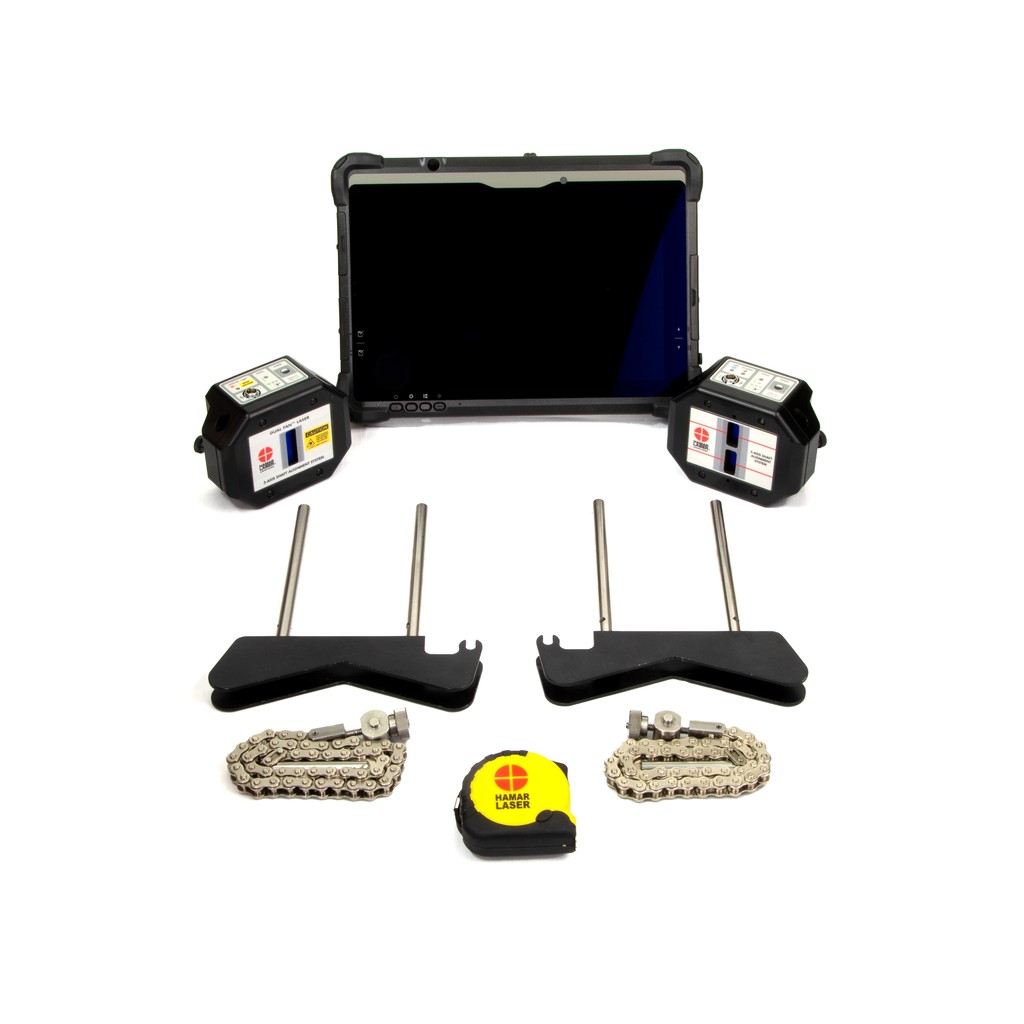
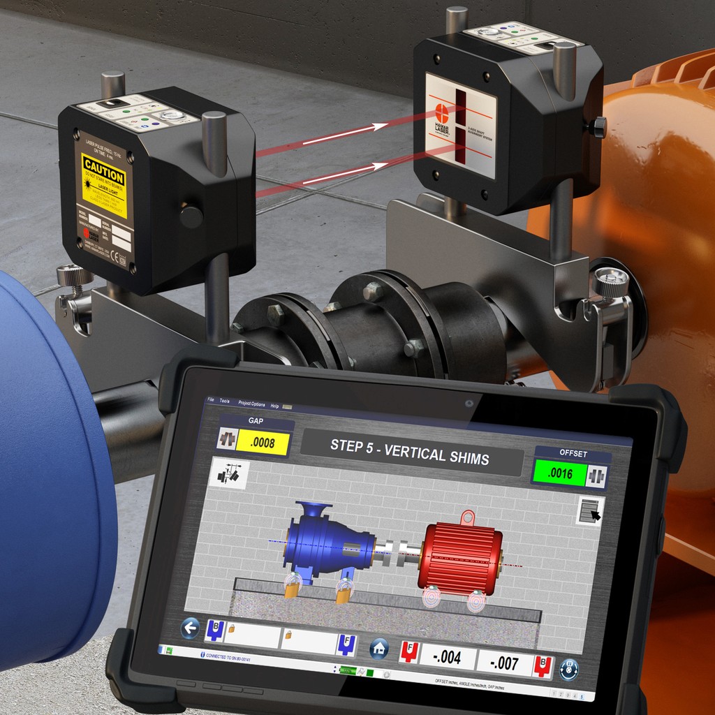





The X-Series™ X-660 3-Axis Laser Shaft Alignment System from Hamar Laser is designed to deliver exceptional accuracy and efficiency in both simple and complex alignment scenarios. Combining advanced laser technology with intuitive software, the X-660 ensures rapid, precise shaft alignment for industries where performance and reliability are non-negotiable.
Built to withstand demanding industrial environments, the X-660 combines cutting-edge laser technology with user-friendly software to reduce alignment time and improve machine reliability. The X-660 is the go-to solution for maintenance professionals seeking to maximize machine uptime, extend equipment longevity, and achieve pinpoint alignment.
The X-660 will meet every expectation:
The X-660 3-Axis Laser Shaft Alignment System from Hamar Laser is designed to deliver exceptional precision and reliability for a wide range of industrial alignment applications. The X-660 sets itself apart in precision alignment solutions by offering a unique Build Your Own (BYO) system, allowing you to customize the applications and capabilities to match your specific operational needs, an option no other brand provides. This innovative approach not only boosts measurement consistency and repeatability but also makes the X-660 an ideal choice for maintenance teams and service providers aiming to minimize downtime and reduce maintenance costs.
Engineered for demanding environments, the X-660 features a rugged, wireless design with IP67-rated alignment heads, ensuring reliable performance even in harsh conditions. The system’s Easy-Guide™ software simplifies the alignment process by guiding users through each step, reducing training time and minimizing the potential for human error. Real-time data feedback and automatic calculation of correction values streamline the alignment process, allowing technicians to make precise adjustments on the spot.
With built-in tools for soft foot detection, thermal growth compensation, and real-time shim and move guidance, Couple6™ ensures that no alignment variable is left unchecked. Data can be captured using a variety of measurement methods including Auto Clock™, Auto Sweep™, and Point Mode™, making it adaptable to different machine configurations and field conditions. Compatibility with rugged Windows® tablets or standard laptops offers unmatched flexibility in the field or in the plant.
Designed to maximize machine uptime and extend equipment life, the X-660 excels at aligning motors, pumps, compressors, and gearboxes. Its ability to deliver real-time alignment data in an easy-to-understand format makes it a valuable tool for achieving optimal alignment accuracy while maintaining operational efficiency. Additionally, comprehensive digital reporting ensures that alignment data is readily available for quality assurance and compliance purposes. The X-660’s robust design, high accuracy, and user-friendly interface make it a trusted solution for industries that require precise and efficient alignment practices.
From its high-resolution sensors to its easy-to-use Easy-Guide™ software, the X-660 is packed with features that speed up alignment tasks while improving measurement consistency.
±8° angular range for fast alignments.
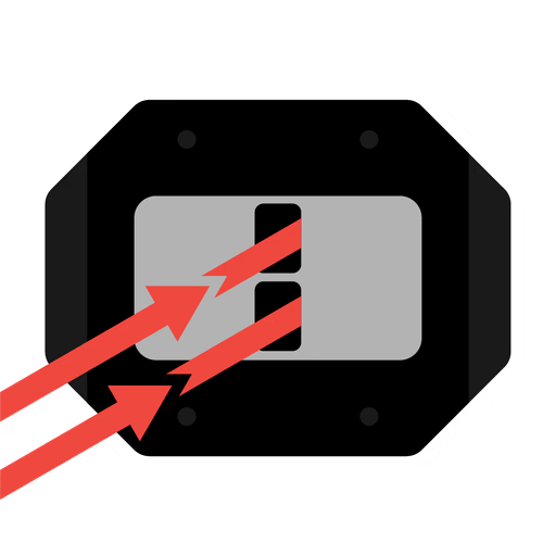
Offers an impressive ±8º angular range using two unidirectional laser fans (2 laser fans, 1 direction), eliminating the rough-in problem of crossfire lasers (2 lasers, 2 directions) and enabling fast, easy alignment, even over long distances. More jobs done, happier managers!
Measure instantly from 2 in. to 15 ft.
Unlike crossfire systems that need pre-alignment, Dual-Fan™ technology with 2 unidirectional laser fans and 20 mm sensors allows you to take data instantly, no rough-in needed. Get the same measuring range from 2 in. to 15 ft., far surpassing crossfire kits that struggle beyond 5 ft. Just set up and start working!
PSD sensor cuts shim calc time in half
Our PSD technology and 60-point sensor linearization reduce target error to <0.75%, up to 5x more accurate than competitors, ensuring reliable alignment, better repeatability, and precise shim calculations. Shim Once, Move Once™!
Maintains precision at every distance.
Unlike crossfire lasers, which lose accuracy at close distances, Dual-Fan™ technology maintains high angular resolution from 2 in. to 15 ft., offering 4x greater precision than typical systems.
On-screen help and training built right in.
Our Couple6™ software with Easy-Guide™ navigation features intuitive, high-quality screens that guide users through every alignment step. Plus, built-in manuals and training videos make it so easy to use that many customers start using the X-660 right out of the box!
Free updates. No hidden costs. Ever.
Our 5-Year Unconditional Warranty means just that, no hidden fees or conditions! If there’s no abuse-related damage, we’ll repair or replace your system if something goes wrong. Plus, unlike other systems, we never charge for software maintenance, updates are free for the life of the product!
No two alignments are the same, and with the X-660, you don’t have to treat them that way. Choose the method that fits your machinery and working conditions.

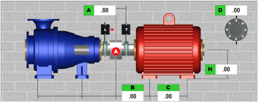
Aligns two rotating machines connected by a single coupling, measuring and correcting both angular and offset misalignments between the shafts to ensure optimal alignment
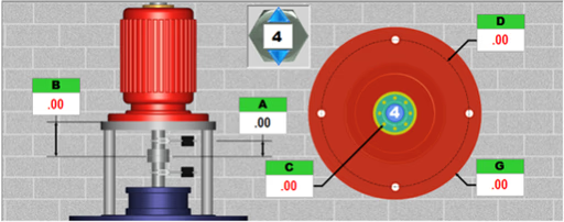
Industry’s only vertical alignment system featuring live graphical displays of motor alignment and shim values for every bolt hole position, specifically designed for flange-mounted vertical motors.
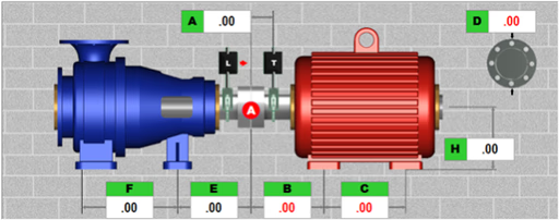
Allows locking and unlocking various combinations of the movable and stationary machine feet to evaluate their impact on the alignment solution. Graphics and shim values update automatically.
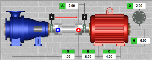
Aligns the shafts of two rotating machines connected by a spacer or jack shaft, ensuring their rotational centerlines are perfectly collinear. This alignment method offers seven different configuration options.
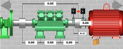
Collects data from 3 to 10 machines and calculates the minimal shim and move adjustments needed, ensuring all shafts are collinear and correctly aligned across the entire machine train.
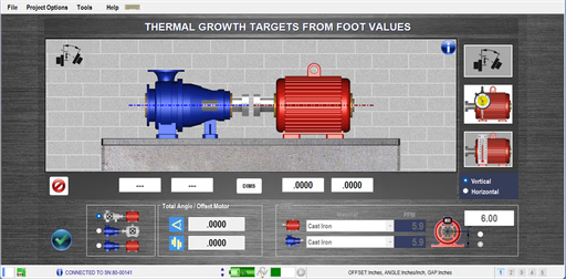
Apply thermal expansion or contraction to the rotating equipment. 3 methods available for thermal compensation: coupler offset, foot values, and temperature change.
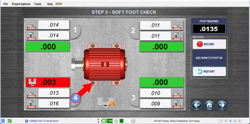
Simple, on-screen guided procedure for checking Soft Foot, an issue that can lead to misalignment. Step #3 alignment workflow, it pinpoints the problematic foot and determines the required shim correction.
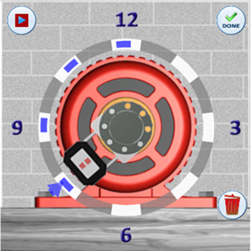
No matter the machinery layout or space limitations, the X-660 provides powerful data-taking tools that eliminate guesswork and improve alignment efficiency.

Offers 8 selectable clock positions, simply rotate the laser or target to the desired position and click record. A minimum of three points spaced 90 degrees apart is required.
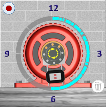
Begin at any clock position and sweep to any other point with a minimum rotation of 60 degrees. The system automatically calculates results when a sweep is completed.
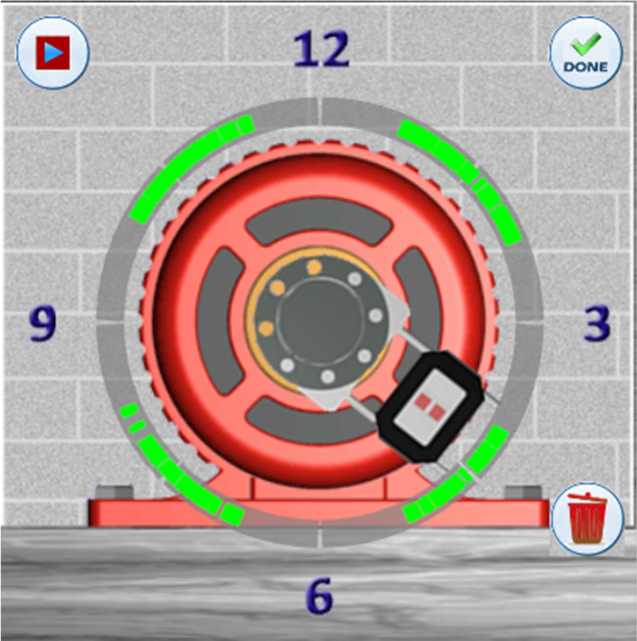
Allows starting and stopping at any point within the rotation circle multiple times, ideal for situations where obstructions block the laser beam or prevent a full rotation.
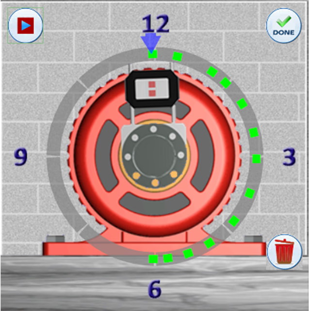
Allows the laser/target to be rotated to any clock position in the sweep, capturing a data point at that specific location. Also suitable for performing uncoupled alignments.

Built for performance and reliability, the X-660 includes all the essential tools and capabilities needed to streamline shaft alignment in any industrial environment.
Click on each icon below to view more information.
Measurement results are automatically evaluated against a built-in tolerance table featuring two levels; Excellent and Acceptable. Alignment conditions are clearly displayed using intuitive color-coding: Green for Excellent, Yellow for Acceptable, and Red for Out of Tolerance. Tolerance values are based on engineering standards developed by industry expert Heinz Bloch, PE.
Enables users to input and save dimensions, tolerances, and coupling types for commonly aligned motor setups. Previously saved alignment files can be reopened to auto-populate key parameters, including Thermal Growth Offset, for faster setup. Streamlines the process: mount components, load the file, perform a soft foot check, collect data, and apply moves or shims as needed.
Allows the screen view to be rotated for correct machine orientation based on the user’s position. Also functions in Zoom mode on the Windows tablet. Originally introduced by Hamar Laser in 1992.
Evaluates data quality and identifies signs of potential bearing wear. Since 2006, our Couple6 alignment software has featured a measurement quality indicator, a series of color-changing dots that reflect data accuracy. Note: This analysis is presented in a safe 2D format, unlike 3D views which can be unsafe to interpret. The emerging trend of using 3D scanning visuals is discouraged, as it can distract users, consume 75% of the screen, and does not enhance the alignment process.
Our Couple6 alignment software produces color reports that can be saved as PDFs and emailed directly from the tablet or Windows PC when connected to the internet.
Store machine data and files, including plant location, machine names, tolerances, and dimensions, all saved dynamically for easy reuse and templating.
Digital signatures on shaft alignment reports ensure data integrity, authenticity, and accountability. They verify the results are accurate and unaltered, support regulatory compliance and audits, and clearly document who performed the work and when. This builds trust and professionalism in the alignment process.
Allows the end user to adjust the recommended tolerance settings to any value needed for their specific application. This flexibility ensures alignment meets the precise standards required by the asset OEM or accommodates unique operational preferences, helping to optimize machinery performance and reliability.
Features realistic graphics with live updates of values as adjustments are made. Displays real-time data and visuals during corrections for vertical machines, allowing quick changes to the reference point with a simple touch. Ideal for vertical equipment adjustable at the flange (non-spigot mounted).
Includes a built-in manual within the Couple6 alignment software that automatically directs you to the exact page corresponding to your current step in the alignment process. You can also easily access the full table of contents to quickly navigate and choose any section you need, providing seamless guidance right when you need it.
The X-660 goes beyond traditional shaft alignment by including optional geometric applications that enhance precision across a wide range of machine setups.

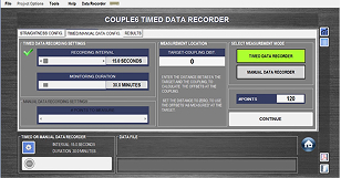
The Manual/Timed Recording App offers both single-point and timed recording modes, capturing data that can be easily exported in Excel format for streamlined analysis. Reports include minimum and maximum values, graphical plots, and comprehensive data tables for clear insight.
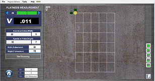
Flatness measurements can be performed using the A-987 Magnetic Swivel Brackets to evaluate sole plates and other critical mounting surfaces. This setup enables accurate, repeatable data collection directly on the asset, supporting proper machine installation and long-term reliability. Couple6 software computes a Best-Fit plane to determine overall flatness, with reports displaying TIR values, graphical plots, and detailed data tables for comprehensive documentation and analysis.
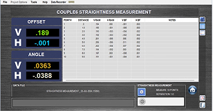
Straightness measurements can be performed using our A-987 Magnetic Swivel Bases along with shaft alignment lasers to evaluate the vertical and horizontal straightness of rails and other surfaces. The Couple6 software calculates a Best-Fit line to determine overall straightness, with detailed reports that include TIR values, graphical representations, and comprehensive data tables.
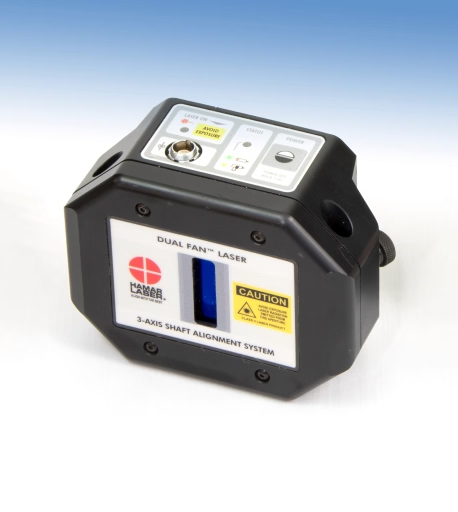
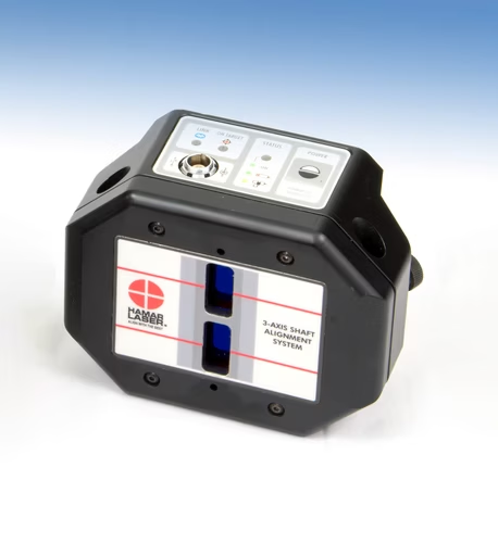
The L-780 Dual-Fan™ Laser Head delivers superior accuracy and safety with ultra-thin, low-divergence laser fans and rugged, waterproof construction. Engineered for extended range and all-day runtime, it’s built to perform in demanding alignment conditions.
The T-1280 Target offers ultra-high resolution with dual-axis PSDs, built-in Bluetooth® wireless, and IP67 waterproof protection, engineered for accuracy in the toughest shaft alignment environments.
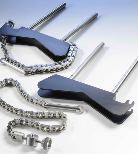
Designed for fast, repeatable shaft setups, the A-970 Aluminum Brackets use quick-connect hardware and rugged components to ensure stability in the field.
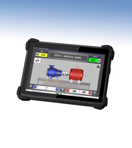
Purpose-built for demanding industrial environments, our rugged tablet is preloaded with Couple6™ and built to perform in the field, rain or shine.
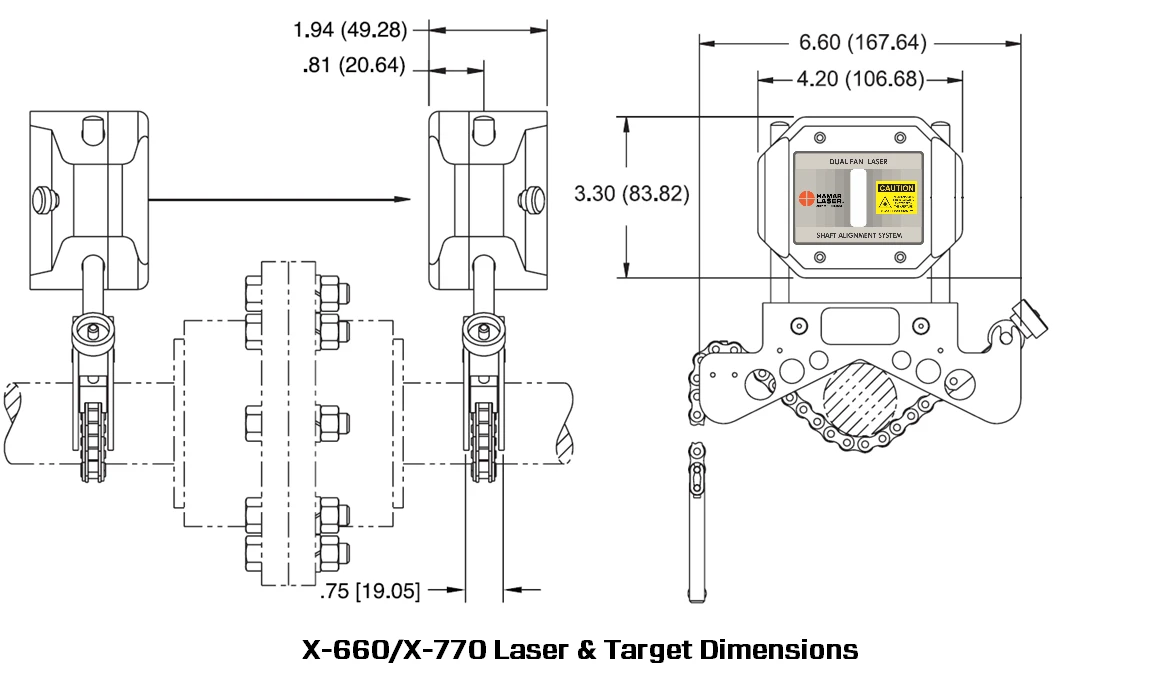
| Laser/Target Unit Size | 4.2x3.3x1.94 in. (107x84x49 mm) |
|---|---|
| Housing Material | Impact resistant plastic |
| Detector Type and Size | Two (2) 1-axis PSDs 20x1 mm provides 2 continuously updating alignment axes (1 alignment plane). |
| Ambient Light Protection | Yes, via blinking-laser algorithm embedded in all Hamar targets |
| Target Measurement Resolution | Offset: .00004 in. (0.001 mm or 1.0 micron) Angular: .00016 in/ft (0.014 mm/m) |
| Target Measurement Error | Offset: < 0.75% Angular: < 1.5% |
| Angular Sensor Range | ± 8° (± .136 in/in or 13.6 mm/100 mm). For values > 4° use only for rough alignment. |
| Laser Type | 650 nm Dual-Fan laser with 0.5° fan < 0.9mW with 2 mm fan "thickness" to enhance measurement range. |
| Wireless Communication | Bluetooth® Class 2 - 2.4-5 GHz |
| Wireless Range | Up to 33 ft. (10 m) under ideal conditions, though physical walls and interference can reduce this indoors. |
| Ruggedized Display Platform | Rugged 10" tablet, IP65, MIL-STD-810G, 2.0 GHz., 8GB RAM/256GB HD. |
| Rotation Sensor (3rd axis) | Accelerometer Resolution: 0.1° Accuracy: ± 1°. Measurement accuracy not affected by rotation sensor accuracy. |
| Environmental | IP67 (laser & target). IP65 (tablet). |
| Bracket Set | Chain Set - up to 6 in. (152.4 mm) shaft diameters Post Set – 6 in. (152.4 mm) long |
| Application Range | 15 ft. (4.57 m) between laser and target |
| Operating/Storage Temperature | Laser/Target: 5° to 140° F (-15° to 60° C) Tablet - AC Mode: -4° to 140° F (-20° to 60° C) Tablet - Battery Mode: 32° to 113° F (0° to 45° C) |
| Battery Life Target | 15 Hours continuous with Bluetooth®, Unlimited with Data/Charging Cable. Target can be plugged into power source during use. Battery status indicator for both target and table |
| Battery Life Laser | 150+ hours continuous use. Unlimited with Data/Charging cable. Blinking LED indicates low battery status. |
| Battery Life Tablets | 8 hours (normal use) |
| AC Battery Charger (Laser and Target) | 110V to 220V with U.S. or international adapters. Cable transfers data and updates Target firmware. |
Legend: √ = Included • = Optional N/A = Not Applicable
| System Features | X-660 | X-770 PRO | X-770 PRO + GEO | X-880 | X-990 PRO | X-990 PRO + GEO |
|---|---|---|---|---|---|---|
| Laser Type | Dual-Fan | Dual-Fan | Dual-Fan | Dual-Beam | Dual-Beam | Dual-Beam |
| Type of Sensor | 1-Axis PSD | 1-Axis PSD | 1-Axis PSD | 2-Axis PSD | 2-Axis PSD | 2-Axis PSD |
| Sensor Size | (2) 20x1 mm | (2) 20x1 mm | (2) 20x1 mm | 33x13 mm | 33x13 mm | 33x13 mm |
| Bluetooth/Wireless Capabilities | √ | √ | √ | √ | √ | √ |
| Laser/Target IP Classification | IP67 | IP67 | IP67 | IP67 | IP67 | IP67 |
| Laser to Target Max Range | 15 ft/4.6 m | 15 ft/4.6 m | 15 ft/4.6 m | 33 ft/10 m | 33 ft/10 m | 33 ft/10 m |
| Battery Life for Target / Laser | 15 / 150 hours | 15 / 150 hours | 15 / 150 hours | 15 / 150 hours | 15 / 150 hours | 15 / 150 hours |
| Rugged Windows® Tablet | • | • | • | • | • | • |
| Build Your Own (BYO) Capability | √ | N/A | N/A | √ | N/A | N/A |
| Professional App License | N/A | √ | √ | N/A | √ | √ |
| Detailed PDF Report | √ | √ | √ | √ | √ | √ |
| Aluminum V-Bracket with 6 in (152.4 mm) diameter chain set | √ | √ | √ | NA | NA | NA |
| Stainless Steel V-Bracket with 6 in (152.4 mm) diameter chain set | • | • | • | √ | √ | √ |
| Extra Chain Set/Diameter Sizes | • | • | • | • | • | • |
| Standard Threaded 6 in. (152.4 mm) Posts | √ | √ | √ | N/A | N/A | N/A |
| Standard Support 4 in. (101.6 mm) and 8 in. (203.2 mm) Posts | • | • | • | √ | √ | √ |
| Extra Post Sets/Sizes | • | • | • | • | • | • |
| Magnetic Shaft Brackets (2) | • | • | • | • | • | • |
| Offset Bracket | • | • | • | • | • | • |
| Non-Rotating Shaft Bracket Assemblies | • | • | • | • | • | • |
| Geo Magnetic Swivel Bases | • | • | √ | • | • | √ |
| Alignment Methods | X-660 | X-770 PRO | X-770 PRO + GEO | X-880 | X-990 PRO | X-990 PRO + GEO |
|---|---|---|---|---|---|---|
| Standard Horizontal Alignments | √ | √ | √ | √ | √ | √ |
| Vertical Flange Mount Alignments | √ | √ | √ | √ | √ | √ |
| Spacer (Jack Shaft) Alignments | • | √ | √ | √ | √ | √ |
| Uncoupled Alignments | N/A | N/A | N/A | • | • | • |
| Bolt Bound/Base Bound Alignments | • | √ | √ | √ | √ | √ |
| Cardan Shaft Alignments | N/A | N/A | N/A | √ | √ | √ |
| Machine Train Alignments (3 Machines) | • | √ | √ | • | √ | √ |
| Machine Train Alignments (Up To 10 Machines) | • | • | • | • | • | • |
| Data Taking Methods | X-660 | X-770 PRO | X-770 PRO + GEO | X-880 | X-990 PRO | X-990 PRO + GEO |
|---|---|---|---|---|---|---|
| Auto Clock™ Data Taking Mode | √ | √ | √ | √ | √ | √ |
| Auto Sweep™ Data Taking Mode | • | √ | √ | √ | √ | √ |
| Arc Mode™ Data Taking Mode | • | √ | √ | • | √ | √ |
| Point Mode™ Data Taking Mode | • | √ | √ | • | √ | √ |
| Uncoupled Swipe™ Data Taking Mode | N/A | N/A | N/A | • | √ | √ |
| Geometric Measurement Applications | X-660 | X-770 PRO | X-770 PRO + GEO | X-880 | X-990 PRO | X-990 PRO + GEO |
|---|---|---|---|---|---|---|
| Manual/Timed Data Recorder/Analyzer | • | • | √ | • | • | √ |
| Flatness Data Recorder/Analyzer | • | • | √ | • | • | √ |
| Straightness Data Recorder/Analyzer | • | • | √ | • | • | √ |
| L-730 Precision Leveling/Flatness Laser (Laser Only) | N/A | N/A | N/A | • | • | • |
| L-740 Ultra Precision Leveling/Flatness Laser System | N/A | N/A | N/A | • | • | • |
| Additional System Information | X-660 | X-770 PRO | X-770 PRO + GEO | X-880 | X-990 PRO | X-990 PRO + GEO |
|---|---|---|---|---|---|---|
| Upgradeable for the Life of the System | √ | √ | √ | √ | √ | √ |
| 2-Year Calibration Requirement | √ | √ | √ | √ | √ | √ |
| 5-Year Unconditional Warranty | √ | √ | √ | √ | √ | √ |
| Angular Sensor Range | ±8º | ±8º | ±8º | ±12º | ±12º | ±12º |
| Preset & User-Defined Tolerances | √ | √ | √ | √ | √ | √ |
| Real-Time Unit (Imperial/Metric) Switching | √ | √ | √ | √ | √ | √ |
| Soft Foot Check | √ | √ | √ | √ | √ | √ |
| Thermal Growth Compensation - Foot Values | √ | √ | √ | √ | √ | √ |
| Thermal Growth Compensation - Coupler Offset | • | √ | √ | • | √ | √ |
| Thermal Growth Compensation - By Temperature | √ | √ | √ | √ | √ | √ |
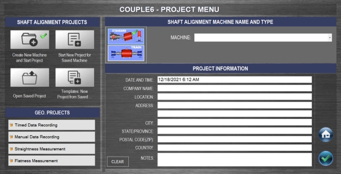
Couple6 creates a project folder for all alignment projects. This allows you to save project files for each machine in a unique folder allowing you to track machine alignments. You can save a machine setup as a template to open for other machines with the same dimensions. Also, you can click on Review Saved Projects to review a saved project. Enter your company information to be included on the reports.
Assumptions for this example: You have a 480 volt motor drawing 40 amps and operating 8400 hours/year. The Power Factor is .85. Electricity costs $0.06/kWhr. Also assume that the amp draw is measured before and after the alignment and it is found that there is a 1 amp difference.
kW =V* A*PF*1.732/1000
kW =480V* 1A*.85*1.732/1000
kW =.706 = power savings
Savings ($) = operating hours * kW savings * kW cost
Savings ($) = 8400 * .706 * $0.06/kWhr
Savings ($) = 355.82
If your plant has 80 similar motors, and if only half of them had the same amount of savings, it would total $355.82 * .5 = $14,232!
The coupling icons next to the data displays show the direction of the misalignment at the coupling and update as you move or shim the motor! You can also zoom in on the coupling to show them in the live display area of the screen.