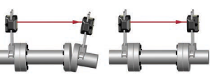
Most laser alignment systems still require a rough-in (or rough-alignment) step before you can even start using the system. That means you are doing part of the alignment manually, before the laser system is even helpful. In other words, you are doing the alignment job twice. And we do not think that sounds very “easy,” especially when you are paying for technology that should streamline your workflow, not slow it down.
Want proof? One Competitor encourages it for every shaft alignment system they make, including their Top-Tier model. Their own manual emphasizes the need for rough alignment before laser measurement can begin, because their “cross-fire” laser technology is sensitive to angular misalignment. You must manually get the motor close before the system can even collect full rotation data.
It is a similar story from another shaft alignment competitor. Their manual devotes five pages, just for pre-alignment procedures only. Why? Again, “cross-fire” lasers struggle when angular misalignment is too high, so you are forced to use other tools like straightedges or dial indicators first.
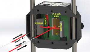
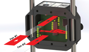
Hamar Laser’s X-Series™ laser shaft alignment systems are designed differently, from the ground up, to save you time and hassle. Our patented Dual-Beam™ and Dual-Fan™ technology combined with extra-large PSDs (Position Sensing Detectors up to 33×13 mm) makes it easy to take data, even during new motor installs or long-distance jobs, without needing a rough-in.
Larger PSDs keep the laser beam on target longer and across wider misalignment ranges. That means you can skip the straightedge, forget about dial indicators, and go straight to data collection. No pre-alignment step. No second round. Just fast, reliable results.
We will be honest: Sure, we allow data collection over a narrow 40° rotation range because customers asked for it, but we do not recommend it. We built X-Series™ to manage real-world applications with precision, not just the bare minimum.
Unidirectional Dual-Beam™ Technology
| Feature | X-Series™ Uni-Directional Technology | Competitor Cross-Fire Lasers |
|---|---|---|
| Rough Alignment | √ No rough alignment required | - Requires manual pre-alignment |
| Setup Speed | √ Fast, one setup | - Slower, often double work |
| Beam Stability | √ Laser stays on target during full rotation and live moves | - Beams easily rotate off PSDs |
| Angular Range | √ ±8° (3-axis) / ±12° (5-axis) | - Limited range; struggles with large offsets |
| Ease of Use | √ Simple, 5-step guided process | - Complex setup; needs extra steps |
| Real-World Reliability | √ Works in vibration, long distances, new motor installs | - Beam loss common in field conditions |
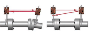
X-Series™ systems use uni-directional lasers (two lasers, one direction), mounted only on the stationary machine. Why is that important? Because competitor systems with “cross-fire” lasers (two lasers firing in opposite directions) can be extremely frustrating, especially on long-distance applications.
As soon as you begin rotating the shafts, the laser beams from “cross-fire” setups easily rotate off the tiny PSD windows. This means the user must first pre-align the machinery just so the laser beams stay on target, and even then, it is easy to lose the beam when making live adjustments.
In contrast, X-Series™ stationary-mounted laser system maintains beam contact with the target during full rotation and during corrections, even on long spans. That is less interruption, less frustration, and no need to redo your setup halfway through a move.

With the most angular range of any laser shaft alignment system, X-Series™ makes new motor installations a breeze. You can drop in your motor, mount the laser and target with zero pre-alignment, and start collecting data, even with large angular offsets. And since we factory-align the laser and target to the brackets, you are ready to go out of the box.
3-Axis – ±8 degrees of angular range (+/- .136″/in. or 13.6 mm/100 mm)
5-Axis – ±12 degrees of angular range (+/- .204″/in. or 20.4 mm/100 mm)
Bottom line:
No rough-alignment tools. No alignment guesswork. Just fast, accurate data from the start.
Assumptions for this example: You have a 480 volt motor drawing 40 amps and operating 8400 hours/year. The Power Factor is .85. Electricity costs $0.06/kWhr. Also assume that the amp draw is measured before and after the alignment and it is found that there is a 1 amp difference.
kW =V* A*PF*1.732/1000
kW =480V* 1A*.85*1.732/1000
kW =.706 = power savings
Savings ($) = operating hours * kW savings * kW cost
Savings ($) = 8400 * .706 * $0.06/kWhr
Savings ($) = 355.82
If your plant has 80 similar motors, and if only half of them had the same amount of savings, it would total $355.82 * .5 = $14,232!
The coupling icons next to the data displays show the direction of the misalignment at the coupling and update as you move or shim the motor! You can also zoom in on the coupling to show them in the live display area of the screen.