

Couple6 Software Virtual Tour
To see the power and simplicity of our Couple6 software, please take an interactive tour by clicking on the tabs below to see details on each Step in the process.
[cq_vc_hotspot image=”4339″ position=”16%|2.6%,54.5%|18.8%,54.5%|74.5%” iconbackground=”rgba(0,0,0,0.01)” circlecolor=”rgba(255,255,255,0.01)” trigger=”click” maxwidth=”800″]
[hotspotitem]
[hotspotitem]
Opening Project Files
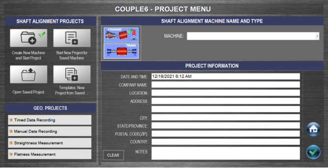
Couple6 creates a project folder for all alignment projects. This allows you to save project files for each machine in a unique folder allowing you to track machine alignments. You can save a machine setup as a template to open for other machines with the same dimensions. Also, you can click on Review Saved Projects to review a saved project. Enter your company information to be included on the reports.
[/hotspotitem]
[hotspotitem]
Software Settings/Preferences
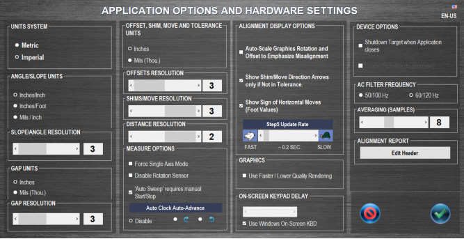
Couple6 gives you very detailed control over how you want the screens to appear with many preference and choices with how to show the data. It even gives you a choice of graphics quality so it will run better on older tablet pcs! You can even edit the report header to include your company logo.
[/hotspotitem]
[hotspotitem]
Print Report Configuration
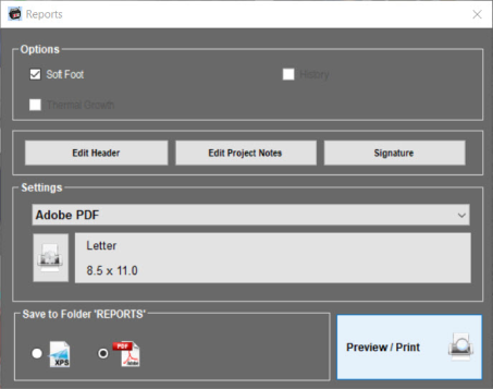
Using the power of Win10, Couple6 can print to any printer, a PDF file or XPS file for emailing or texting reports. You can also choose to include or not include Soft Foot, Thermal Growth Data or History. Click here to see a Couple6 Sample Report.
[/hotspotitem][/cq_vc_hotspot]
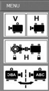
To navigate between the 5 main alignment steps, manage project files, print reports and change alignment settings, just click on the tabs above to see details for each Step.
[cq_vc_hotspot image=”4366″ position=”12.5%|91.5%,48.5%|75.5%,67.5%|75.5%,78%|89.5%,55%|69.5%,67%|53%” iconbackground=”rgba(255,255,255,0.01)” circlecolor=”rgba(255,255,255,0.01)” trigger=”click” maxwidth=”800″ marginoffset=”300px 0px 0px 0px”][hotspotitem]
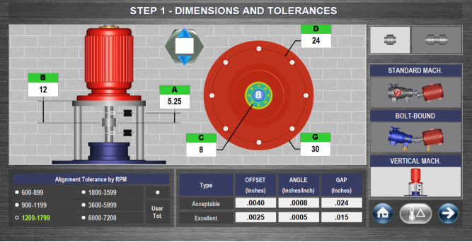
Choose Vertical Machines™ alignment type and the vertical pump graphics will display. Select the number of bolts and enter the dimensions on the screen and after taking the data, Couple6 will automatically calculate the dimensions at each bolt hole location. Couple6 also offers the industry’s only live vertical machine alignment screen (shown in Step 5).

Home Button takes you to the main navigation screen.
Next button takes you to Step 2.
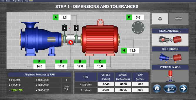
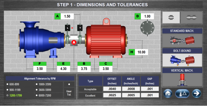
Enter machine dimensions as shown on the screen. Accuracy of 0.25 inches (0.5 mm) is all that is needed for accurate shim calculation. Enter the coupling diameter (D dimension) and Couple6 will convert gap tolerances to the match the coupling diameter.
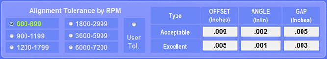
Choose RPM to select tolerance to apply to the motor. The table shows both Acceptable and Excellent Tolerances. The Gap tolerance is automatically converted to match the coupling diameter dimension entered (D dimension). If User-Defined Tolerances is enabled, the user can change the tolerances to customize them to their internal specs.
Coupling Type
![]()
Choosing Spacer Shafts changes the dimension graphics, adding the G dimension, which requires entering the length of the spacer coupling. This also automatically changes the data output to the default Spacer Shaft format
![]()
Couple6 has 7 different spacer shaft data formats that can be displayed in Step 5 and the report to match the many different tolerance formats in the industry.
[/hotspotitem]
[hotspotitem]
Choose Bolt Bound™ alignment type and the pump side dimensions are added to the dimension screen. Enter the pump dimensions and when you get to the move screen, you can lock and unlock different combinations of motor/pump feet to see which combination minimizes the moves. To learn more about the Bolt Bound™ features of Couple6™ check out this Alignment Byte™™ features of Couple6™ check out this Alignment Byte™
[/hotspotitem]
[hotspotitem]
 [/hotspotitem]
[hotspotitem]
Navigation Icons and Thermal Growth in Step 1

Home Button takes you to the main navigation screen.
Next button takes you to Step 2.
[/hotspotitem]
[hotspotitem]
Dimensions – Standard Motor
[/hotspotitem]
[hotspotitem]
Select Alignment Tolerance
[/hotspotitem][/cq_vc_hotspot]
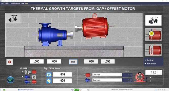
In the MOTOR SETUP SCREEN the motor’s foot dimensions, machine description and desired alignment tolerances are entered. Choose the coupling type (flexible or spacer) and alignment type (Standard, Bolt Bound Vertical Pumps or Machine Trains).
Thermal growth offsets (the amount the motor grows from a cold start to operating temperature) are also entered at this stage by clicking on the Thermal Growth icon  and opening the modeling screen.
Navigate between the 5 main alignment steps, manage project files, print reports and change alignment settings.
[cq_vc_hotspot image=”4373″ position=”27.4%|84.5%,44.5%|84.5%,71%|22%,71%|44%” iconbackground=”rgba(255,255,255,0.01)” circlecolor=”rgba(255,255,255,0.01)” trigger=”click” maxwidth=”500″][hotspotitem]
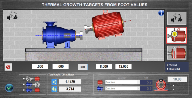
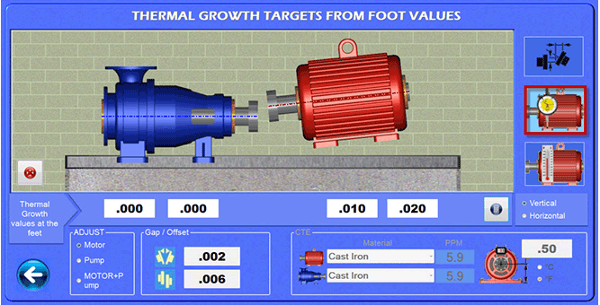
Enter Thermal Growth values at the motor’s feet and Couple6 will calculate how much that will affect the alignment at the coupling, will update the motor graphics to show what direction the motor moves and will automatically apply these offsets to the alignment. Foot values can also be entered on the pump side for both the vertical and horizontal axes. To learn more about Thermal Growth check out this Alignment Byte™
Thermal growth offsets can be applied to the horizontal axis as well.
[/hotspotitem]
[hotspotitem]
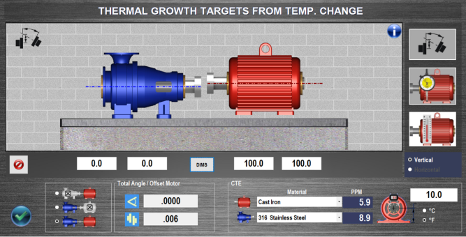
Thermal Growth Foot Calculator From Temp Change
Enter temperature changes at each foot, the height of the shaft from the motor base and select the material type of the motor and Couple6 will calculate how much each foot will grow and automatically calculate how much this affects the alignment at the coupling. The motor graphics will also update to show how this affects the alignment. Values can be applied to the pump or motor side or both.
Coefficient of Thermal Expansion (CFE)
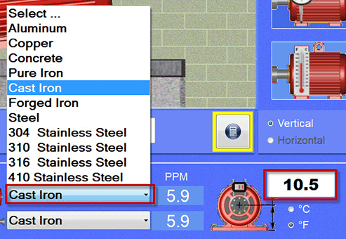
Here is the CFE calculator. Pick the material type and Couple6 automatically applies the coefficient of thermal expansion to the motor or pump. Enter the dimension from the center of the shaft to the machine base. Hit the calculator and it converts the temp changes to coupling values.
[/hotspotitem]
[hotspotitem]
Thermal Growth Foot Calculator
You can enter the temperature changes for both the motor and pump and Couple6 will convert this complex situation into a simple thermal growth offset at the coupling and apply it automatically to the alignment values.
[/hotspotitem]
[hotspotitem]
Thermal Growth at the Coupling
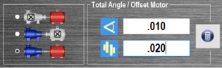
Enter thermal growth values at the coupling and Couple6 will move the motor graphics to show how much the motor’s feet will move. Values can be also applied to the motor or the pump side.
After hitting the calculator button
![]()
Couple6 shows how much the feet move for this offset. The graphics update to show which direction the motor moves.
[/hotspotitem][/cq_vc_hotspot]
Thermal Growth is an optional screen and is not included in the 5 main steps in Couple6. It can be opened by clicking on the Thermal Growth Icon in the Step 1 Dimensions Screen.
Enter thermal growth offsets in Coupling Mode or Foot Mode and go back to Dimension Screen and Couple6 will automatically apply these offsets to the alignment in Step 5. So after aligning the machine, with these offsets applied, the motor will be “misaligned” by the offset value. This means when the motor (or pump) gets up to operating temperature, it will “grow” into alignment.
Values can be entered either at the feet or the coupling. There is also a foot calculator where you can enter the foot temperatures and the material type and Couple6 will calculate how much the feet will grow and how much this will affect the alignment at the coupling and the feet.
All thermal growth offsets can be applied to the horizontal axis too!
[cq_vc_hotspot image=”4380″ position=”19%|25%,19%|43.5%,53%|67.5%,” iconbackground=”rgba(255,255,255,0.01)” circlecolor=”rgba(255,255,255,0.01)” trigger=”click” maxwidth=”800″][hotspotitem]
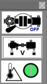
Live 4-Axis Readout
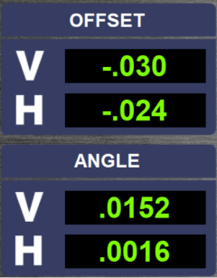
Offsets – With the X-880/X-990, Couple6 shows live displays in the Vertical and Horizontal axes. Values should be less than .040″ (1 mm) for maximum offset measurement range. For the X-660/X-770, only the Vertical axis is shown.
Angular – With the X-880/X-990, Couple6 shows live displays in the Vertical and Horizontal axes. Values should be less than .015 in./inch (1 mm/100 mm) for maximum angular measurement range. For the S-670, only the Vertical axis is shown.
No More Rough-In Alignment!
Normally, with the large measuring range of the X-Series™ it is not needed but in cases where large motors are installed, this screen is used to “rough in” the motor’s large angular misalignment so the laser can take data for the final alignment. For the vertical axis, simply rotate the laser from 12:00 to 6:00 and average the 2 angular readings, which gives you the rough angular misalignment in inches/inch or mm/100 mm. Multiply this by the C dimension from Step 1 and add or subtract the result from the front or back feet to align the angle of the motor. Repeat this for the Horizontal axis by rotating the laser from 3:00 to 9:00.
[/hotspotitem]
[hotspotitem]
Laser Setup – Horizontal Adjustment
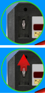 When the horizontal offset value is not within +/- .040″ (1 mm) of zero, a Red Arrow displays on the screen to show you which direction to turn the adjustment wheel.
As the Horizontal Offset Value nears zero, the arrow color changes to yellow to indicate that’s “good enough” and disappears altogether if it’s within .010″ of zero.
[/hotspotitem]
[hotspotitem]
Laser Setup – Live Graphical display
![]() Live alignment graphics illustrate how far from the center of the PSD (dotted circle), the laser beams are. The beam graphics move on the screen as you adjust the laser beam to show you are getting closer to the center. A color-coded arrow shows which direction to slide the target up/down on the brackets. However, you can still take data if the beams are not aligned.
Live alignment graphics illustrate how far from the center of the PSD (dotted circle), the laser beams are. The beam graphics move on the screen as you adjust the laser beam to show you are getting closer to the center. A color-coded arrow shows which direction to slide the target up/down on the brackets. However, you can still take data if the beams are not aligned.
For the T-1290 target, the display is live in both the Vertical and Horizontal axis. When the lasers are within .020″ (0.5 mm) of zero, the arrow turns green and the laser dots are centered in the dotted circles indicating you are done.
[/hotspotitem][/cq_vc_hotspot]
With our X-880/X-990, the Step 2 Laser Setup Screen provides a live display in all 4 alignment axes (2 measurement planes) to adjust the laser or target to maximize the measurement range of the target. However, the system can still be used even if the laser beams are not aligned.
With on-screen instructions, the user is directed to adjust the laser to bring the readings within +/- .040″ (1 mm) of zero. Adjustments to the Vertical Offset are made by moving the laser up or down on the brackets. Adjustments to the Horizontal Offset are made by turning a wheel on the front of the laser. Couple6 automatically tells you which direction to adjust the wheel to bring the offset values into alignment
No More Rough-In Alignment!
Normally, with the large measuring range of the X-Series™ , it is not needed but in cases where large motors are installed, this screen can be used to “rough in” the motor’s angular misalignment so the laser can take data for the final alignment. For the vertical axis, simply rotate the laser from 12:00 to 6:00 and average the 2 angular readings, which gives you the rough angular misalignment in inches/inch or mm/100 mm. Multiply this by the C dimension from Step 1 and add or subtract the result from the front or back feet to align the angle of the motor. Repeat this for the Horizontal axis by rotating the laser from 3:00 to 9:00.
[cq_vc_hotspot image=”4412″ position=”14%|27.5%,14%|50%,68%|53%,68%|27%,32%|40%” iconbackground=”rgba(255,255,255,0.01)” circlecolor=”rgba(255,255,255,0.01)” trigger=”click” maxwidth=”800″][hotspotitem]
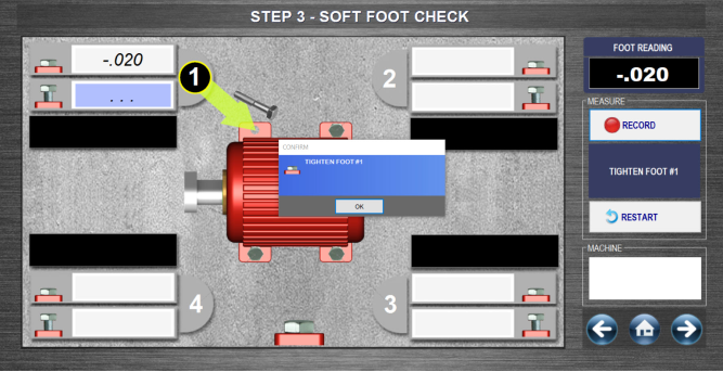
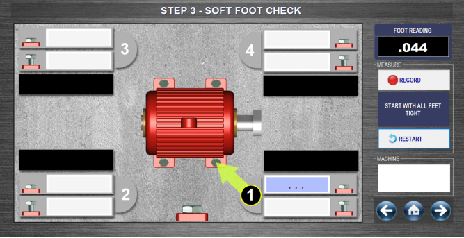
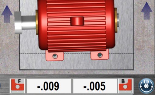
Soft Foot – Foot #1 Results

Follow the on-screen instructions and make sure all bolts are tight! Then hit Record with the bolt for Foot #1 tight, loosen it, and hit Record again. Couple6 calculates the difference between the 2 data points and if out of tolerance will flag it as red. Green means it’s in tolerance. After taking the tight reading, a message reminds you to tighten the foot. When you hit OK it automatically takes you to Foot #2
[/hotspotitem]
[hotspotitem]
Soft Foot – Foot #2 Results

After recording Foot #1 soft-foot results, Couple6 automatically advances to Foot #2. With the bolt for Foot #2 tight, hit Record, loosen it, and hit Record again. As before, Couple6 calculates the difference between the 2 data points and if out of tolerance will flag it as red.
Notice the bolt icon at Foot #2 has changed showing that Couple6 is expecting a “loose” reading.
[/hotspotitem]
[hotspotitem]
Soft Foot – Foot #3 Results

After recording Foot #2 soft-foot results, Couple6 automatically advances to Foot #3. With Bolt #3 tight, hit Record, loosen it, and hit Record again. As before, Couple6 calculates the difference between the 2 data points and if out of tolerance will flag it as red.
Notice now that the difference between readings for Bolt #3 is now red, indicating it is out of tolerance. Again a message pops up reminding you to tight Bolt #3.
[/hotspotitem]
[hotspotitem]
Soft Foot – Foot #4 & Final Results
After recording Foot #3 soft-foot results, Couple6 automatically advances to Foot #4. With the bolt at Foot #4 tight, hit Record, loosen it, and hit Record again. As before, Couple6 calculates the difference between the 2 data points and if out of tolerance will flag it as red.
Now Couple6 finds the foot with the bigger difference between tight and loose and it recommends the amount of shim to add to fix the problem. A shim icon tells you it’s time to add shim and again the on-screen instructions tell you what to do. Simple!
[/hotspotitem]
[hotspotitem]
Soft Foot – Motor Flipped
Using our unique Flip-It™ feature, you can double tap the screen and the motor’s shaft/coupling will flip to the other side. So if you are on the wrong side of the machine you don’t have to turn the tablet upside down! Did someone say, “Simple”?
[/hotspotitem][/cq_vc_hotspot]
Our Soft Foot Check & Correct Screen displays an easy-to-follow soft-foot routine that finds potential soft-foot problems and recommends corrective action. We do the calculations for you!
To use the Soft Foot Screen, simply hit Record with the bolt tight. Then loosen it and take a second reading. Couple6 will then record the difference. Repeat this for all 4 feet and Couple6 will find the foot with the biggest difference and if it is greater than the tolerance, it will recommend the shim to add to fix it.
[cq_vc_hotspot image=”4432″ position=”12%|8.2%,79.5%|4.5%,80%|11%,80%|17%,80%|31%,15%|77%,63%|44%,79%|50.5%,83%|57.5%,83%|66%,90%|95%” iconbackground=”rgba(255,255,255,0.01)” circlecolor=”rgba(255,255,255,0.01)” trigger=”click” maxwidth=”800″][hotspotitem]
Couple6 provides 3-5 axes of live alignment data in our Step 4 -Measure Misalignment screen.
Here the Horizontal Offset is too far from zero and Couple6 changes the display to red to warn you to try to get the horizontal offset closer. It will still take data but it is always best to start near zero to maximize the data-taking range.
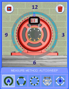
Color-Coded Graphics for Data Quality
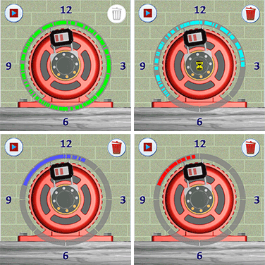
When using the main data-taking mode, Auto Sweep™, Couple6 displays each data point recorded in a color-coded display ring around the motor image. Red means there is not enough data to get good alignment results, blue means data quality is good, light blue means very good and green means the data quality is excellent. For the best repeatability or high-accuracy applications, very good or excellent data quality is highly recommended but a minimum of 60 degrees of data is all that is needed.
[/hotspotitem]
[hotspotitem]
Auto Sweep™ Data-Taking Mode
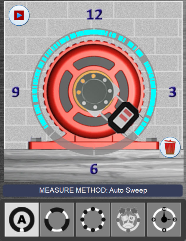
By far, the most popular data-taking mode, Auto Sweep™ makes taking shaft alignment data extremely easy. Simply start rotating the shafts and Couple6 automatically starts recording hundreds of data points at a rate of 16 readings per second, providing the most accurate alignment data in the industry! Most of our competitors only offer 3 points of data, which is not enough! It is an established fact that more data points mean more accurate alignment results. Higher accuracy means quicker alignments and more “coffee breaks”! Stop rotating and Couple6 senses this, calculates the alignment data and pops up the Measurement Results window. To learn more about Auto Sweep™ check this Alignment Byte™ out.
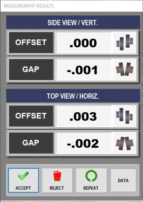
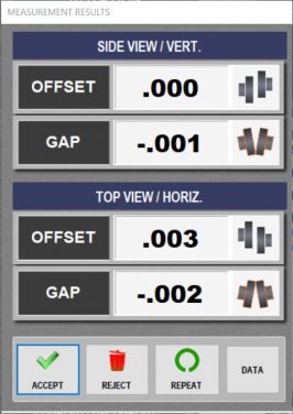
The Measurements Results window displays the alignment results and asks whether to Accept, Reject or Repeat the data. Coupling graphics also tell which direction the coupling is misaligned.
Click Accept to accept the data and save the data in the Repeatability Table. Click on Repeat to accept the data, save it in the Repeatability Table and go back to AutoSweep™ to take another set of data. Click Reject to delete the data and start over.
[/hotspotitem]
[hotspotitem]
Arc Mode™ Data-Taking Mode
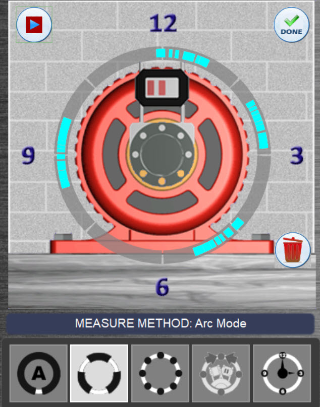
For those applications where parts of the driven unit are preventing you from taking a full rotationset of data (360 degrees), Arc Mode™is a great data-taking mode to get more data and better results. Simply hit the start button and start to rotate the shafts (just like Auto Sweep™)andArc Mode collects data at a rate of 16 readings per second. When the laser/target reach an area where the laser is blocked, just hit the Stop button and when you get beyond the obstruction, hit the Start button to resume recording data.
It is a proven fact that the more rotational data you can get (i.e. 180–360 degrees), the more accurate your alignment results will be. So instead of only having a short arc of data points (say 90 degree arc), Arc Mode™ allows you to get multiple arcs of data giving you more accurate results.
When you are done taking data, click the Done button and Couple6 will calculate the results and popup the Measurement Results screen.
The Measurement Results window displays the alignment results and asks whether to Accept, Reject or Repeat the data. Coupling graphics also tell which direction the coupling is misaligned.
Click Accept to keep the data and save the data in the Repeatability Table. Click on Repeat to accept the data, save it in the Repeatability Table and go back to Arc Mode to take another set of data. Click Reject to delete the data and start over.
[/hotspotitem]
[hotspotitem]
Point Mode Data-Taking Mode
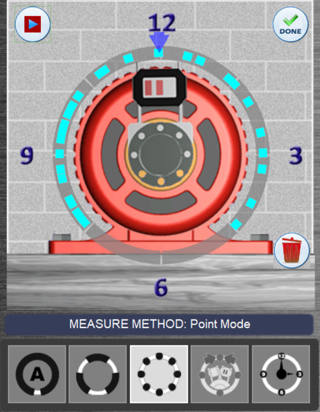
Point Mode is yet another data-taking method that ensures all challenging applications have a solution in Couple6. It is used where you can only take single points of data, typically when there are high levels vibrations present that affect repeatability of our sweep data-taking modes. The data is averaged to dampen out fluctuations caused by vibration and the averaging can be adjusted for high-vibration environments.
Using Point Mode is extremely easy: just rotate the laser/target to any clock position, wait a second or 2 for the data to stop updating and press the spacebar or click Record. Continue until you have the data quality that you want (again the data points are color coded for quality).
When you are done taking data, click the Done button and Couple6 will calculate the alignment results and popup the Measurement Results screen. To learn more about PointMode check this Alignment Byte™ out.

The Measurement Results window displays the alignment results and asks whether to Accept, Reject or Repeat the data. Coupling graphics also tell which direction the coupling is misaligned.
Click Accept to accept the data and save the data in the Repeatability Table. Click on Repeat to accept the data, save it in the Repeatability Table and go back to Point Mode to take another set of data. Click Reject to delete the data and start over
[/hotspotitem]
[hotspotitem]
Auto Clock™ Data-Taking Mode
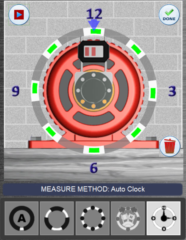
Auto Clock™is the basic data-taking mode in Couple6 used with our entry-level system, the X-660. It is very user-friendly and offers up to 8-data points, unlike the competitions “clock modes” that only offer 3 data points. It is an established fact that more data points means more accurate alignment data. More accurate alignment data means quicker alignments and more “coffee breaks”!.
To use Auto Clock™, just rotate to any “clock” position and hit the Record button or press the spacebar and Couple6 will record the data point. You need at least 3 points to get a valid set of data but at least 5 points is recommended and 8 points will give the best results, especially for high-accuracy applications.
When you are done taking data, click the Done button and Couple6 will calculate the alignment results and popup the Measurement Results screen.
The Measurement Results window displays the alignment results and asks whether to Accept, Reject or Repeat the data. Coupling graphics also tell which direction the coupling is misaligned.
Click Accept to accept the data and save the data in the Repeatability Table. Click on Repeat to accept the data, save it in the Repeatability Table and go back to Auto Clock™ Mode to take another set of data. Click Reject to delete the data and start over
[/hotspotitem]
[hotspotitem]
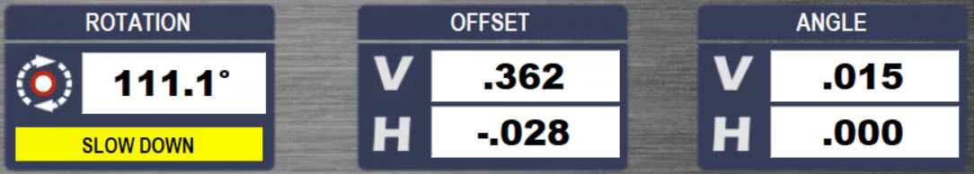
Step 4 Live Alignment Data Displays

This is the Rotation Axis (3rd or 5th axis) Live Display and Status Bar. It shows the continuously updating rotational position of the target. Zero degrees means the target is located at 12:00, 90 degrees means 3:00. The data taking status is also shown here.
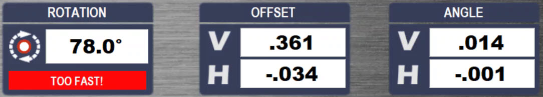
Here the user is rotating the shafts a little too fast using AutoSweep™ or Arc Mode™ and Couple6 is recommending to slow it down. While it will still take data, it is better to rotate slowly to ensure data quality.
Here the user is rotating the shafts much too fast using AutoSweep™ or Arc Mode™, which could affect repeatability and data quality. While Couple6 will still take data in at this speed, it is strongly recommended that you check repeatability to ensure the data is good.
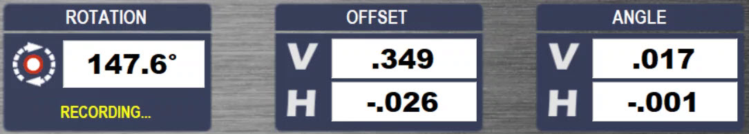
Here the user is recording data at the proper speed in Auto Sweep™ or Arc Mode™
 Here are the 4 axes (T-1290) live alignment data. It is always a good idea to keep an eye on the raw data while recording to make sure no bad data points get into the data set. This can also be used to do a “poor man’s” uncoupled alignment using Point Mode or Auto Clock™
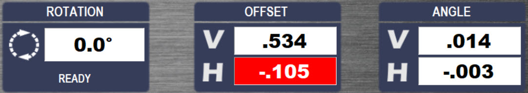
 Here the Horizontal Offset is too far from zero and Couple6 changes the display to red to warn you to try to get the horizontal offset closer. It will still take data but it is always best to start near zero to maximize the data-taking range.
[/hotspotitem]
[hotspotitem]
Repeatability Table
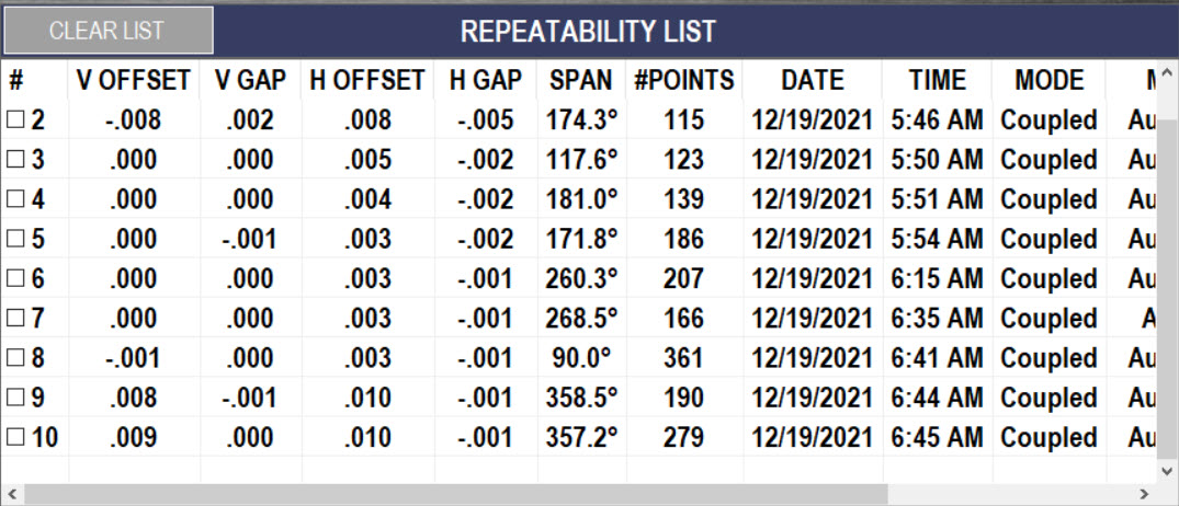
After hitting Accept to save the set of data, Couple6 automatically puts it in the Repeatability Table where you can see the V & H Offsets and V & H Gaps or Angles (go to Settings to change this) and the data of the measurement. You can save up to 20 sets of data in one table.
Click on a set of data to highlight it and hit the Results button to open a window to view the alignment data with tolerances applied to see if it is in or out of tolerance. If you click on the check box on the left for multiple sets of data, Couple6 will average them and use the averaged data for the move screen. You can also add a set of data to the History Table.
[/hotspotitem]
[hotspotitem]
Uncoupled Swipe Mode Data-Taking Mode
Uncoupled SwipeMode, is the best uncoupled data-taking mode on the market, making it extremely easy to take uncoupled alignment data. To take data, simply rotate the laser to any “clock” position, leave it there and slowly rotate or “swipe” the target by the laser and Couple6 will record multiple data points and save the best one based upon a proprietary algorithm. Continue on until your data quality is good.
When you are done, click the Done button and Couple6 will calculate the alignment results and popup the Measurement Results screen. To learn more about UncoupledSwipeMode check out this Alignment Byte™

Couple6 is always trying to make your life easier. Here we have on-screen graphics that show you how to use Uncoupled Mode. Leave the laser at any clock “position” and swipe the target by to record the data point.
The Measurement Results window displays the alignment results and asks whether to Accept, Reject or Repeat the data. Coupling graphics also tell which direction the coupling is misaligned.
Click Accept to accept the data and save the data in the Repeatability Table. Click on Repeat to accept the data, save it in the Repeatability Table and go back to Uncoupled Mode to take another set of data. Click Reject to delete the data and start over
[/hotspotitem]
[hotspotitem]
Measurement Results Screen
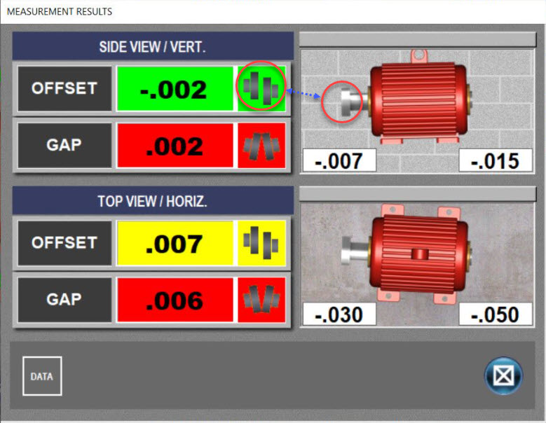
Clicking on a set of data in the Repeatability Table and clicking Results opens up the Measurement Results popup, showing the alignment with the tolerances applied to the data. Red means the data is out of tolerance, yellow means the data is within Acceptable tolerances and green means the data is within Excellent tolerances. Coupling graphics show which direction the motor is misaligned. The shim/move values are also shown for the front and back feet.
[/hotspotitem]
[hotspotitem]
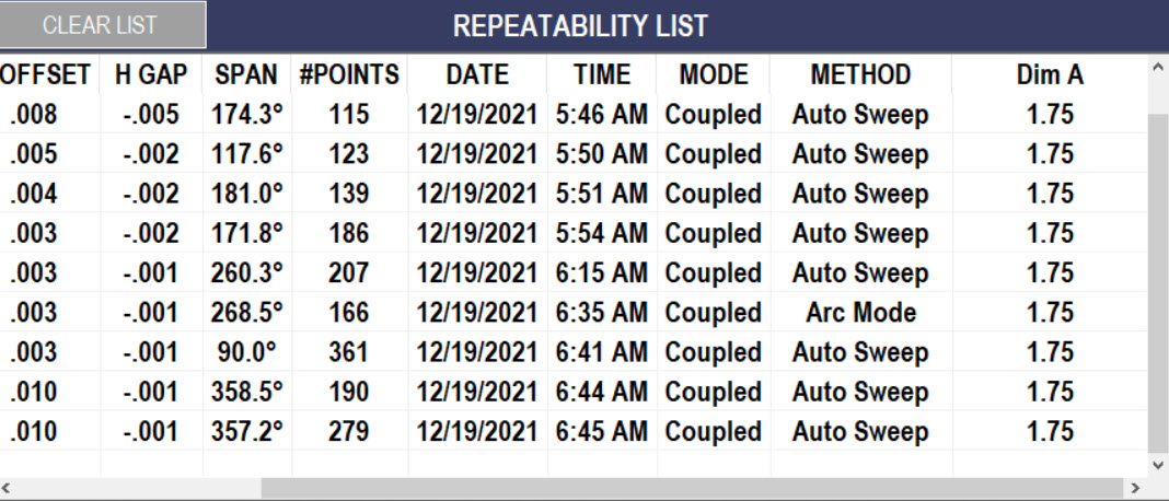
Measurement History Table
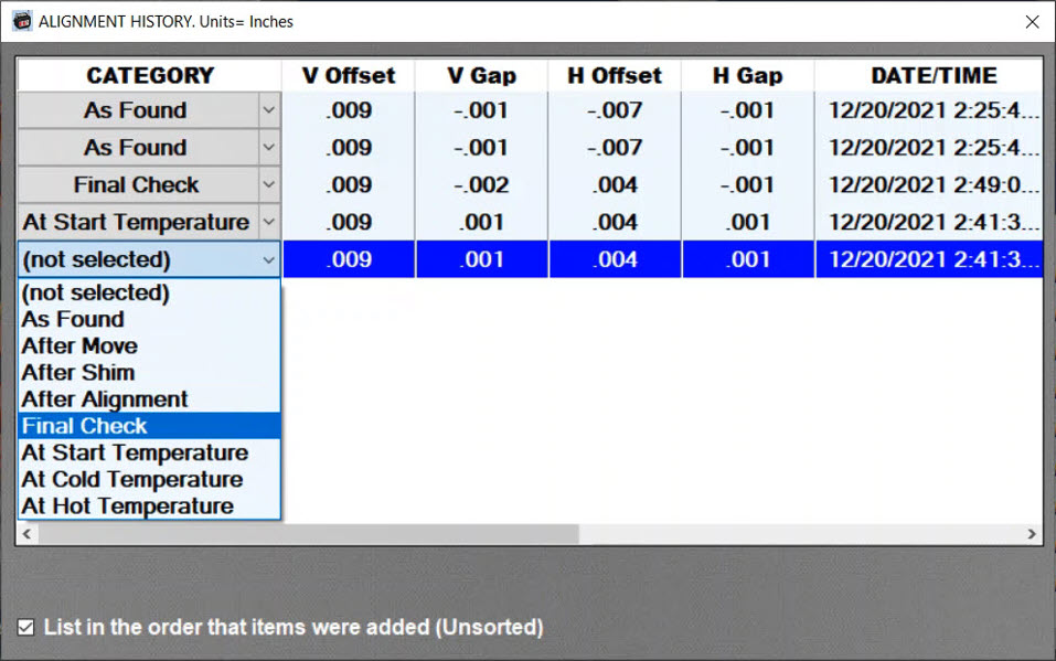
Click on Add to History and Couple6 will save the set of data in the History Table. Up to 50 sets of measurement data (from multiple sets of alignment files for the same machine) can be added to the history table. You can assign the measurement condition to each set of alignment, such as: As Found, After Move, At Hot Temperature, etc. The date and time of measurement are saved along with other important information.
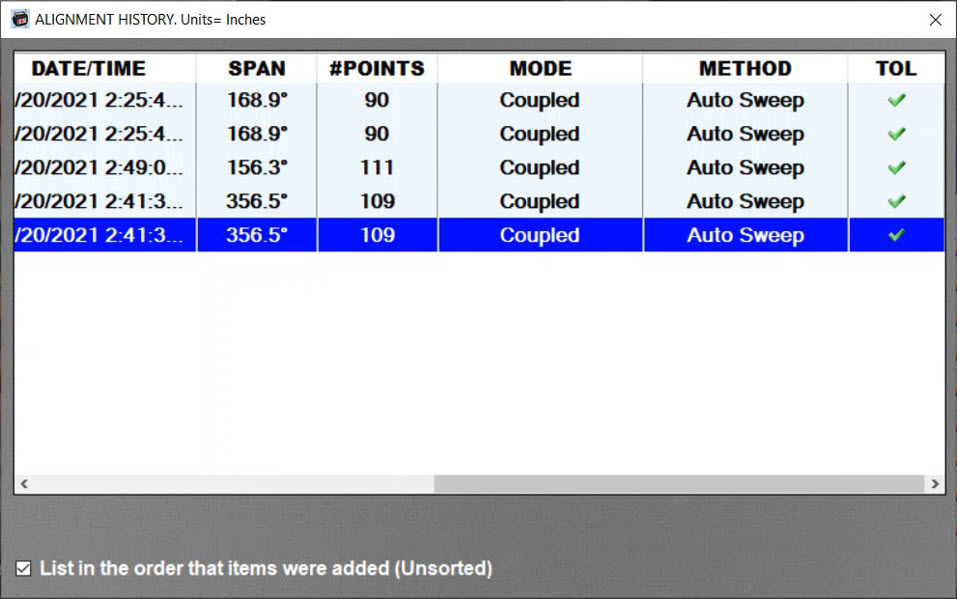
Scroll to the right and the History Table will show the Data Span, Number of Points, Coupling Mode, Data Taking Method, and whether it was in or out of tolerance.
[/hotspotitem]
[hotspotitem]
Go To Move Screen
click on a set of data and if the alignment results are out of tolerance, then click on the Shim Icon to go to the 5-Axis (2 measurement plane) live move screen in Step 5.
[/hotspotitem][/cq_vc_hotspot]
Couple6 offers FIVE different data-taking modes to handle any kind of shaft alignment application. The most popular data-taking mode is Auto Sweep™ which makes taking data extremely easy. Just rotate the shafts and data is automatically taken!
Once the data is taken, Couple6 pops up a window showing the data and if accepted, it will then be put into the Repeatability Table for comparison to previous sets of data. Then highlight a set of data and click the Results button to see the results with tolerances applied. Multiple sets of data can also be averaged and used for the alignment if repeatability is a problem. Data can also be added to History for archiving purposes.
[cq_vc_hotspot image=”4461″ position=”1%|1%,25%|9%,14%|23%,48%|3%,47%|41%,68%|23%,16%|73%,30%|61%,25%|90%,80%|73%,82%|95%” iconbackground=”rgba(255,255,255,0.01)” circlecolor=”rgba(255,255,255,0.26)” trigger=”click” maxwidth=”500″ extra_class=”tip-container-popup”][hotspotitem]
Coupling Icons Show Misalignment
The coupling icons next to the data displays show the direction of the misalignment at the coupling and update as you move or shim the motor! You can also zoom in on the coupling to show them in the live display area of the screen.
[/hotspotitem]
[hotspotitem]
Switching Angular Display Units
Click on this popup to change from Gap Mode (top graphic) to Angular Mode. The units for angular mode are inches/inch, inches/ft, mm/100 mm or mm/M and the units for Gap Mode are inches or mm. After hitting close, the V & H angular displays automatically change to the new format and the label updates, too.

Here is the Vertical angular axis in Gap Mode.

Here is the Vertical angular axis in Angle Mode.
[/hotspotitem]
[hotspotitem]
Vertical Live Data Displays

Vertical Gap (Angle) and Vertical Offset values update continuously in Step 5. A red display means it’s out of tolerance, yellow means it’s in Acceptable tolerance and green means it’s in Excellent tolerance. A positive offset value means the motor is high and a positive angle or gap means the back of the motor is higher than the front.
[/hotspotitem]
[hotspotitem]
Step 5 – Coupling Zoom-In Move Mode
Click on the View Mode button to switch the Step 5 Move screen into Coupling Mode which zooms in on the coupling and shows the alignment at the coupling. This is especially useful for new users of lasers who are used to indicator-based methods and working at the coupling. The graphics automatically update with each move of the motor so you can watch the 2 coupling halves come into alignment as you move it!
[/hotspotitem]
[hotspotitem]
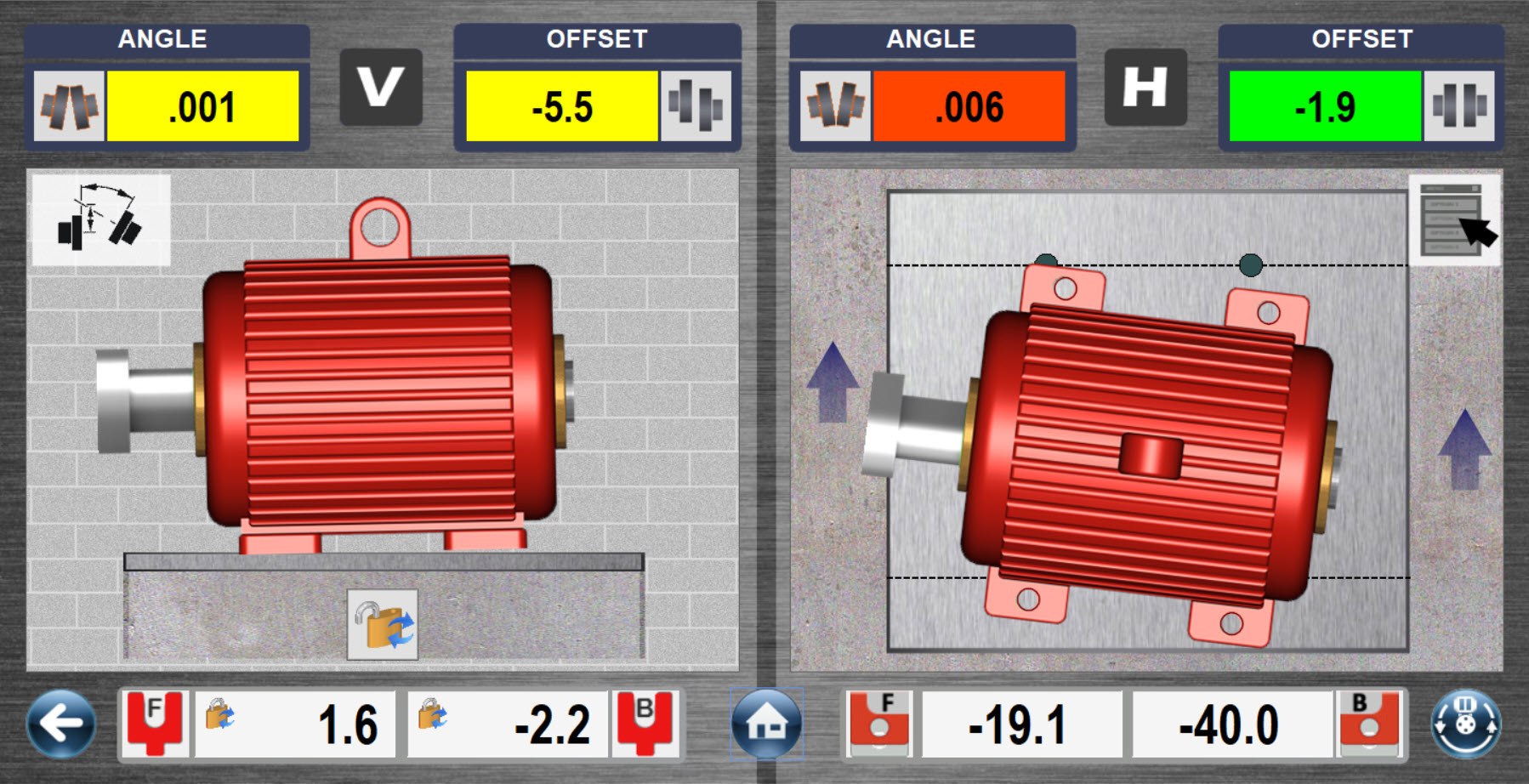
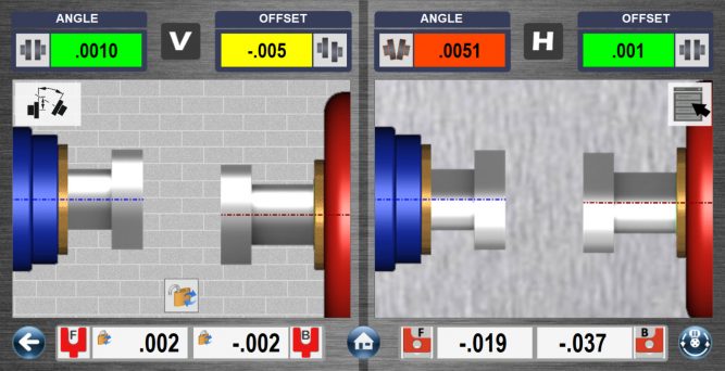
Duo-Plane™ Live Move Screen
Here is our unique Duo–Plane™ Live Move Screen using the T-1290 5-Axis target from the X-880/X-990. It shows all 4 alignment axes (2 measurement planes) updating simultaneously. The displays are color coded to indicate if the alignment is in or out of tolerance. Red means out of tolerance, yellow means it’s in Acceptable tolerance and green means it’s in Excellent Tolerance. The motor graphics move and also update as you align the motor.
Now if you find yourself on the other side of the motor and want to see the graphics appear as you see it then you can utilize our very popular Flip-It™ feature. Simply click on the menu icon and select Flip-It™ and the images flip over – see the image below! No more turning the screen upside down to match your view!
[/hotspotitem]
[hotspotitem]
Vertical Shim Value Displays
![]()
Shim values for the motor are automatically calculated when entering Step 5. The values are locked so you don’t have to remember them but can be unlocked by clicking on the lock icon if you want to see them update. Arrows also tell you which direction the motor needs to go. Down arrows mean to take out shims and up means to add them
[/hotspotitem]
[hotspotitem]
Horizontal Live Data Displays
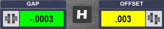
Horizontal Gap (Angle) and Horizontal Offset values update continuously in Step 5. A red display means it’s out of tolerance, yellow means it’s in Acceptable tolerance and green means it’s in Excellent tolerance. A positive offset value means the motor is to the right of the driven unit (with the coupling on the left in top view) and a positive angle or gap means the back of the motor is further right than the front.
[/hotspotitem]
[hotspotitem]
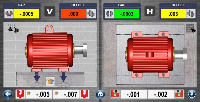
Duo-Plane™ Live Move Screen – Horizontal Foot
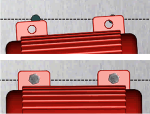
For the Horizontal Axis, Couple6 uses dotted lines and bolt holes to show you where the motor’s feet need to be moved to be in alignment. Once the motor is aligned, Couple6 puts “bolts” into the holes to indicate you are done! Time to take a break!
[/hotspotitem]
[hotspotitem]
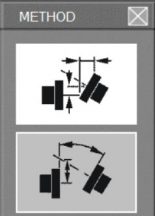
Display Screen Menu

Couple6 gives you lots of options to view the motor graphics in Step 5. A convenient on-screen menu allows you to make this selection very quickly. Click on this icon to popup a menu to choose various changes to the display, such as Coupling Zoom, Bolt Bound™ view, etc. See below for details.
Screen Menu Popup
Click here to bring you back to Duo-Plane™ Mode.
Click here to view the Horizontal Axis for Bolt Bound™
Click here to use the very popular Flip-It™ feature to flip the motor image if you are on the wrong side.
Click here to see the Coupling Zoom feature.
Click here to view the Horizontal Axis for Bolt Bound™
Click here to turn on/off the Thermal Growth values from Step 1.
[/hotspotitem]
[hotspotitem]
Horizontal Move Values
Move values for the motor are automatically calculated when entering Step 5. The values automatically update as you move the motor in the horizontal axis. Arrows also tell you which direction the motor needs to go. Up arrows mean to move the motor away from you and down arrows mean to move it toward you. Once you see the bolt heads appear and the arrows disappear you are done!
[/hotspotitem]
[hotspotitem]
Navigation buttons

Re-Measure Button – Click here to go back to Step 4 and Re-Measure the alignment to confrim it is in tolerance. This is very important!

Home Button – Click here to go to the main menu page to switch Steps or to Print a report.
[/hotspotitem][/cq_vc_hotspot]
Utilizing our Duo-Plane™ live move screen, Couple6 simultaneously shows both the side and top views of the motor’s alignment and displays 4 continuously updating alignment axes (2 alignment planes) on the same screen. Even better, arrows on the display tell you which way to move the motor and the graphic update with each move of the motor! The displays are color-coded to indicate if the alignment is out of tolerance (red), in Acceptable tolerance (yellow) or Excellent tolerance (green).
The angular values can be displayed as angles or gap with a click of the button. And our uniqueFlip-It™feature allows you to flip the motor if you find yourself on the wrong side. The data-updating speed (averaging) can also be adjusted to smooth out fluctuations in the readings due to air turbulence or vibration.

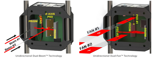
More About X-Series™ Technology…
The X-Series™ range of shaft alignment products are the undisputable best accuracy shaft alignment system on the market today.
read more...
 read more...
Couple6 Easy Guide™…
In just 5-Steps Couple6™ software featuring Easy Guide™ navigation leads users to the fastest precision alignment available today. Learn more, and take the Couple6™ tour today.